Å@
Yoshiaki Sekine1, Tatsushi Akazaki1,
and Junsaku Nitta2,3
1Physical Science Laboratory, 2Tohoku University, 3CREST-JST
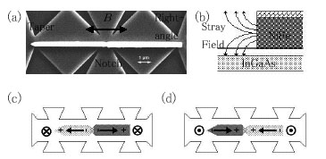
Å@Using the local Hall effect (LHE), we have succeeded in detecting a magnetic
domain wall (DW) trapped in a permalloy, NiFe, wire and in clearly distinguishing
whether the DW structure is a tail-to-tail or a head-to-head DW [1].
Å@In the field of spintronics, devices utilizing DWs were proposed and
many methods were applied to detect DWs. Among them, the LHE method
using a semiconductor and ferromagnetic hybrid structure has the advantage
of large signal enough to investigate the DW dynamics. An InGaAs
two-dimensional electron gas (2DEG) that is 5 nm below the surface was
used for a Hall sensor that detects the stray field from the NiFe wire.
A 60-nm-thick and 300-nm-wide NiFe wire consisting of a notch at the center,
a taper end and a right-angle end was deposited on the surface. These
wire structures make it possible to trap a tail-to-tail or a head-to-head
DW at the notch with changing the direction of the magnetic field, B. Three Hall crosses were fabricated just below both ends and the
center of the wire. Figures 1(a) and (b) show a scanning electron
microscopy (SEM) image and a cross-sectional view of the sample, respectively.
A tail-to-tail DW and a head-to-head DW are sketched in Fig. 1(c) and (d).
With sweeping B parallel both to the wire and the 2DEG, the DW nucleates at the right-angle
end, then the DW displaces to and pins at the notch. With changing
B furthermore, the DW depins from the notch, then the DW moves to and annihilates
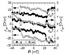
at the right-angle end. The B-dependence
of the Hall resistivity, r
yx, on three Hall crosses is shown in Fig. 2. Here, r yx1, 2, 3 are defined as ryx on the right-angle end, notch, and taper end, respectively. With
increasing B, ryx1 shows the sharp drop at 22 mT, which corresponds to the DW nucleation
at the right-angle end. At 26 mT, rapid increase of ryx3 represents the DW annihilation at the taper end. Between 22 and
26 mT,
ryx2 shows the peak, which corresponds to the pinned tail-to-tail DW.
With decreasing B, the sharp
changes in ryx1 and 3 represent the DW nucleation and annhilation. Between -22
and -26 mT, the dip of ryx2 corresponds to the pinned head-to-head DW. Note that the DW nucleates
at the right-angle end with sweeping B. The LHE method can make the distinction between the tail-to-tail
and head-to-head DWs. These results indicate the LHE method is attractive
for investigating the DW movement that is a key to DW devices.
[1] Y. Sekine, et al., AIP Conference Proceedings 893 (2007)
1291.
 |
 |
|||||
|
Å@Å@ |
|