Å@
Optical Science Laboratory
Å@Å@A periodic chain of optical resonators (coupled resonator optical waveguide:
CROW) is expected to be a promising candidate as a slow light medium [1].
In the last annual report, we mentioned that CROWs composed of ultrahigh
quality factor (Q, Å`106) Si photonic crystal (PhC) resonators [2] could couple more than 60 resonators
with a very low propagation loss, which is a unique advantage of the PC-CROW
[3]. We also reported the dispersion of the PC-CROWs, which corresponded
to a very low group velocity (vg) [3]. In this work, we greatly improved the passband spectrum of PC-CROW
to realize distortion-free short pulse propagation because a short pulse
occupies a wide frequency range.
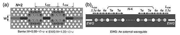
Å@Å@Figure 1 is a schematic of the improved PC-CROW structure. We employed
an inline coupling structure to maximize the coupling between the CROW
and external waveguides. In addition, the resonator interval was apodized
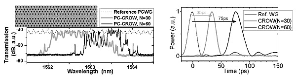
for the same purpose. The passband exhibited close to the ideal low loss,
and was wide and flat as shown in Fig. 2. We performed a time domain pulse
propagation experiment using a short pulse (FWHM: 16 ps, wavelength: Å`1563
nm). The pulse was transmitted through the CROW and was delayed by 35 ps
(N=30) and 75 ps (N=60), respectively (N: resonators in CROW), which agreed well with the vg of 0.0085c (c: light speed in a vacuum) evaluated by dispersion measurement (Fig. 3).
The delay was several times larger than the original pulse width, which
is unachievable with existing slow light media. Moreover, the pulse distortion
and the ringing after-pulse were well suppressed. The results [4] clearly
demonstrated the feasibility of a PC-CROW as a slow light medium for high-speed
optical communication.
Å@Å@This work was partly supported by CREST of the Japan Science and Technology
Agency.
[1] A. Yariv, et al., Opt. Lett. 24 (1999) 711.
[2] E. Kuramochi, et al., Appl. Phys. Lett. 88 (2006) 041112.
[3] E. Kuramochi, et al., CLEO/QELS2007, Baltimore, U.S.A., May 2007, 2.
[4] E. Kuramochi, et al., CLEO/QELS2008, San Jose, U.S.A., May 2008, 3.
 |
||
|
 |
|||||
|