


New method for digital operations using micro machine technology
- An in-plane spring performs multiple logic operations in parallel -
NTT Basic Research Laboratories have developed a new method for digital operations that makes it possible to perform multiple logic operations using a very small flat spring fabricated with micro machine technology. By using this technology, even an entire logic circuit can be constructed with a single device. A conventional computer requires a number of transistors even for the smallest scale logic operation. The new method developed here uses only a single small flat spring of 1.4 µm thickness. A periodic voltage is applied to the spring and this generates a small vibration with amplitude of about 10 nm. By inputting numerous channels of time series data to the device, we succeeded in achieving plural logic operations in parallel.
In the future, we will examine the applicability of this method to larger scale arbitrary logic circuits and undertake a basic evaluation of the device characteristics such as its operating speed and power consumption. These tests will confirm its practical applicability.
These results relate to one of the basic technologies needed to realize a "nano-machine computer", which promises low power consumption and good environmental stability. This report will be published in the electronic edition of the UK scientific magazine, "Nature Communications" on February 15. Part of this work received support from the Japan Society for the Promotion of Science (JSPS).
=> Nanostructure Technology Research Group
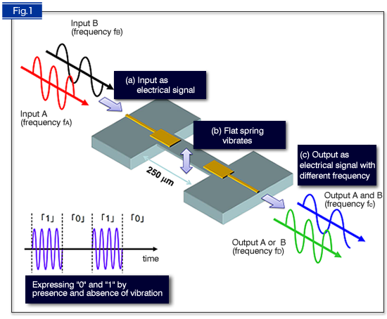
Fig. 1 Conceptual diagram of logic operation by frequency conversion
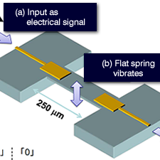
1. Digital signals (A and B) encoded with binary information are inputted into the electrodes of the device (a) as AC electrical signals with different frequencies (fA and fB).
2. An electric signal causes the flat spring to vibrate (b) thus generating new signals with different frequencies (fC and fD).
3. The vibration with frequency fC is generated only when the input signal is fed into A and B simultaneously, while the vibration with frequency fD is generated when the input signal is fed into both or one of the inputs A and/or B. These vibrations (fC and fD) correspond to the logic operations of “A and B” and “A or B”, respectively.
4. The obtained vibration is transferred to the electric signal again and is outputted from another electrode (c).
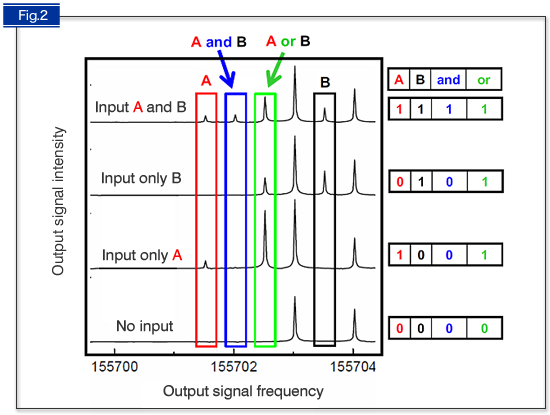
Fig. 2 Example of an actual operation
The figure shows the spectrum of the output signal. The frequency region shown in blue is seen when both A and B are input, while that shown in green is seen when one or both of the signals (A and/or B) is input. This behavior confirms that "A and B" or "A or B" operation has been simultaneously achieved. This is the simplest example, and we have experimentally achieved more complex logic circuit operations, including A or (B and C) in a three-input system known as a majority-logic gate.